
Blog
How Does a Pneumatic Forging Hammer Work?
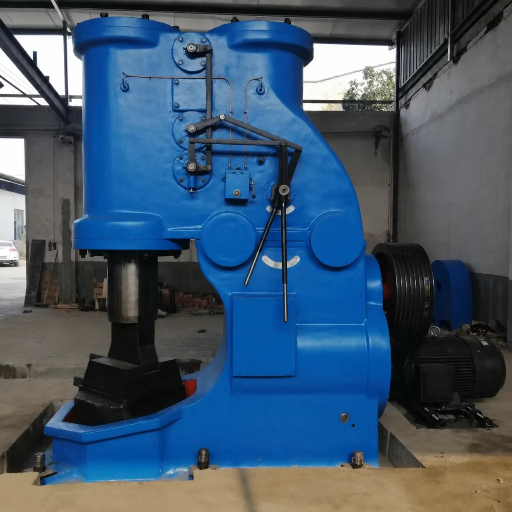
A pneumatic forging hammer uses a motor-driven compressor and working-cylinder arrangement to raise and drive a ram that delivers repeated blows to heated metal. The operator controls the hammering action while repositioning the workpiece between the upper and lower dies.
This guide explains the working principle without assuming a particular model or what appears in the accompanying video. For available machine capacities, visit our pneumatic forging hammer page.
What Is the Basic Working Principle?
The machine converts electrical energy from the motor into mechanical rotation, then uses the crank and compressor piston to create alternating air pressure. Controlled air movement acts on the working piston and ram, producing the lifting and downward hammering strokes.
The heated billet is placed on the lower die. Each downward movement transfers impact energy through the upper die into the workpiece. Repeated blows progressively change the metal’s cross-section, length or shape.
Which Systems Create and Control the Forging Blow?
1. Electric Motor and Drive
The motor powers the hammer mechanism through a suitable transmission arrangement. Motor capacity and electrical specification must match the hammer design and the factory supply.
Correct rotation, electrical protection and stable power are essential for reliable operation.
2. Compressor Cylinder
The compressor cylinder produces the alternating pressure conditions used by the working cylinder. This integrated arrangement is why a self-contained pneumatic forging hammer does not normally rely on a separate plant air compressor for its hammering stroke.
Seals, cylinder condition and lubrication influence air efficiency and control response.
3. Working Cylinder and Piston
The working cylinder receives controlled air from the compressor side. Pressure acting above or below the working piston raises, holds or drives the ram according to the operating control position.
The working surfaces and seals must be maintained within the manufacturer’s specified tolerances.
4. Ram and Upper Die
The ram carries the upper die and transmits the downward blow. Ram guidance helps maintain alignment so the upper and lower dies meet correctly.
Excessive guide wear, loose die fixing or poor alignment can affect forging quality and increase stress on the machine.
5. Anvil, Lower Die and Foundation
The lower die supports the workpiece while the anvil and foundation absorb and distribute repeated impact. These are part of the operating system, not merely installation accessories.
Foundation design should reflect hammer size, ground conditions, local vibration requirements and the machine supplier’s data.
6. Operator Control
What Happens During a Forging Cycle?
The operator uses the control arrangement to start, stop and vary the hammering action. Light blows can assist positioning and finishing, while stronger blows provide primary deformation.
Actual response depends on hammer design, maintenance condition, tooling, workpiece temperature and operator technique.
| Stage | Machine Action | Process Purpose |
|---|---|---|
| Workpiece positioning | Ram held or light control applied | Place the hot billet safely on the lower die |
| Initial blows | Controlled repeated impact | Establish contact and begin deformation |
| Primary forging | Stronger blows with repositioning | Draw, upset, flatten or form the billet |
| Intermediate handling | Hammer paused or controlled | Rotate, feed or reheat the workpiece |
| Finishing | Lighter controlled blows | Refine shape and dimensions |
| Removal | Ram secured in a safe position | Transfer the forging for cooling or the next process |
The exact cycle must be developed for the component, material, temperature range and tooling.
How Is Forging Force Controlled?
A pneumatic hammer does not operate as a single fixed-force device. The operator can vary the control input and therefore the behaviour of the working piston and ram. This permits different blow intensities within the machine’s designed operating range.
The useful forging effect also depends on ram or falling-part mass, stroke behaviour, die contact, workpiece temperature, material resistance and the amount of deformation attempted per blow. Capacity comparisons should therefore use full technical data rather than one headline figure.
How Does the Hammer Integrate with Heating and Handling?
The hammer requires correctly heated stock and timely transfer. A production arrangement may use a furnace or induction heater, temperature measurement, tongs, lifting equipment, a manipulator, dies, cooling racks and inspection equipment.
Long transfer delays can allow the billet to cool below the preferred forging range. Heating capacity, distance to the hammer, handling speed and the number of reheats should be reviewed together.
What Data Is Required to Confirm the Working Configuration?
Provide the material grade, billet dimensions and weight, finished-part drawing, maximum forged section, intended operations, required output and available heating method. Also provide factory voltage, frequency, floor and foundation information, installation space and the proposed handling method.
If special dies or a manipulator are required, include workpiece gripping surfaces, temperature, rotation requirement and maximum transfer distance.
Frequently Asked Questions
Does the hammer use compressed air?
Yes. A pneumatic forging hammer uses controlled air pressure within its compressor and working cylinders to operate the ram.
Is an external compressor required?
A self-contained design normally creates its own working air. Confirm the services needed for any auxiliary equipment included in the final line.
How can the operator change blow intensity?
The operating control regulates the pneumatic action so the hammer can deliver lighter or stronger blows within its designed range.
Why is the foundation important?
The foundation supports alignment and distributes repeated impact into the ground. An unsuitable foundation can contribute to vibration, movement and poor operation.
What causes inconsistent hammer performance?
Possible factors include incorrect adjustment, air leakage, worn seals or guides, poor lubrication, loose tooling, unsuitable billet temperature or unstable electrical supply.
Can the process be automated?
Heating, transfer and workpiece handling can be mechanised or partly automated, but the arrangement must be engineered around the workpiece and forging sequence.
Technical Review of the Hammer and Forging Process
Correct machine selection requires a review of the entire energy path, from the motor and pneumatic mechanism through the ram, dies, workpiece, anvil and foundation.
Send Wiz Forging Machinery your component drawing, billet data, material, process and output target for review. Request a quotation or explore our pneumatic forging hammer machinery.